HTB Cyber Apocalypse 2023 - (Hardware) Secret Code
‘Secret Code’ was one of the challenges in the ‘Hardware’ category at HTB’s Cyber Apocalypse 2023. Its difficulty was “Easy”.
This is a story about how I used Excel to solve a challenge about PCBs :)
For this challenges we got an archive containing a bunch of .gbr files and a .sal file (the ZIP was created by me).
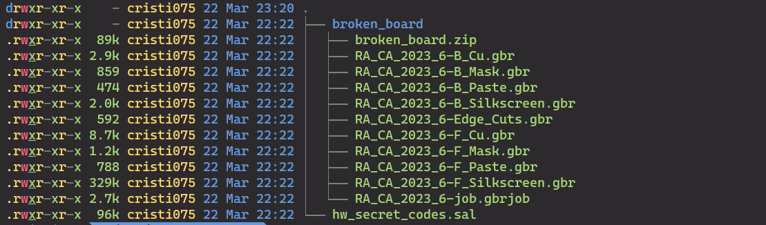
From the previous challenges (Critical Flight and Debug), we already know that the .gbr files describe PCBs and the .sal file is a capture from a logic analyzer that can be opened with Logic2.
First, I start with the .sal file and opened it in Logic2.
There, I could see 8 signals.
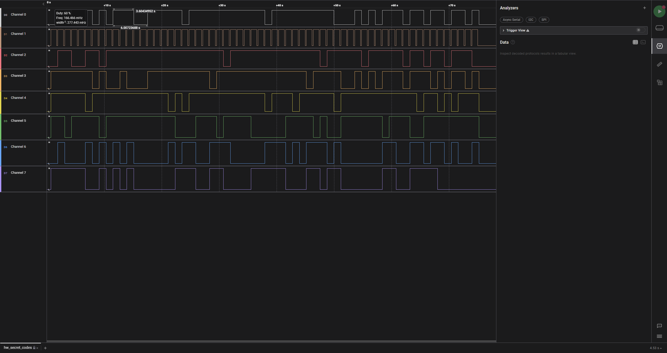
The only thing that looks familiar is Signal1 which seems to act as a clock signal.
This is also hinted in the challenge text: The device is transmitting a new character every second
Let’s also take a look at the PCB files using the same online viewer as before:
https://www.pcbway.com/project/OnlineGerberViewer.html
We have a basic circuit. Like in the previous challenge, let’s try to look through the layers.
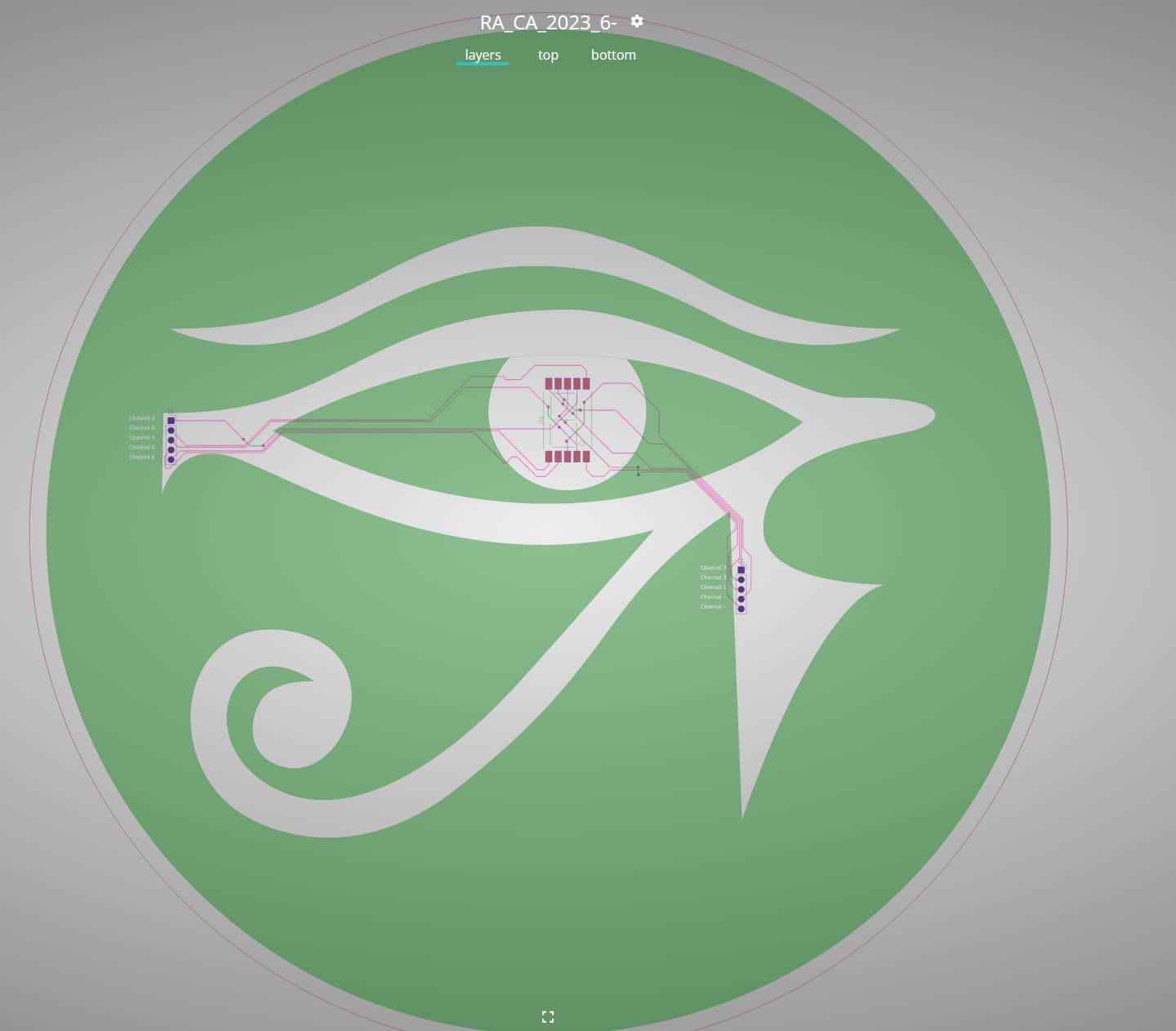
I couldn’t find any fragments of the flag or hints. But, when looking at the circuit in the center I noticed something familiar.
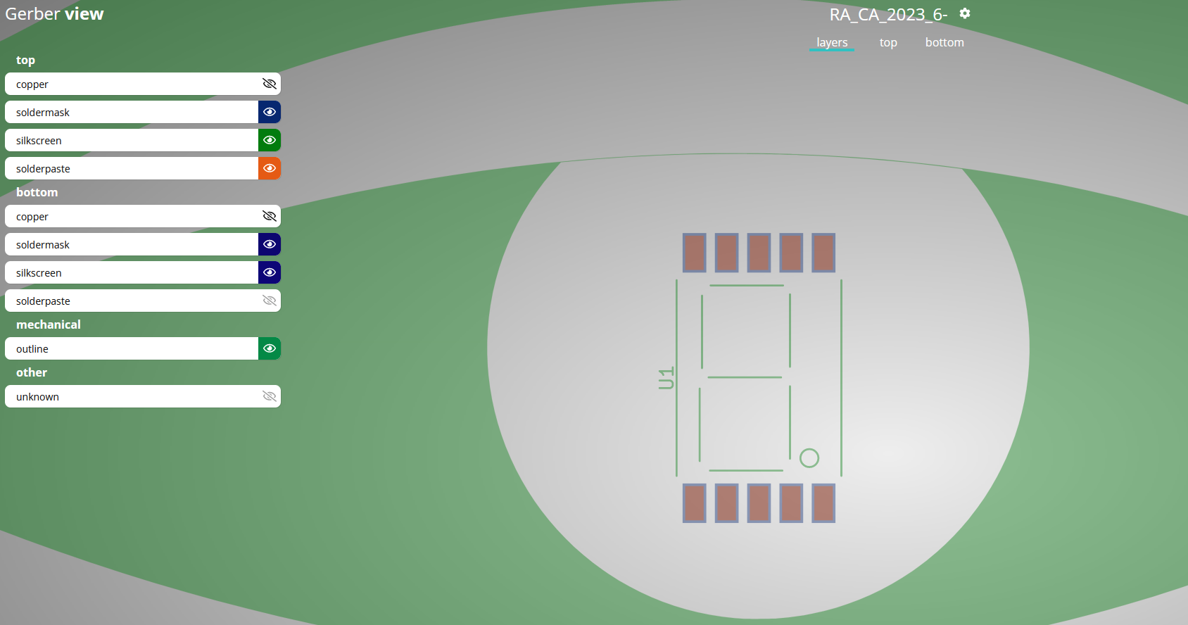
That seems to be a seven segment display.
It also has 10 inputs: 2 of them are GND and VCC (those don’t carry information, they’re for powering up the circuit) and the other 8 signals are probably the ones from the Logic2 capture.
The seven segment display is probably used to display a new character from the flag each second.
Let’s export the data out of Logic2 so we can work with it:
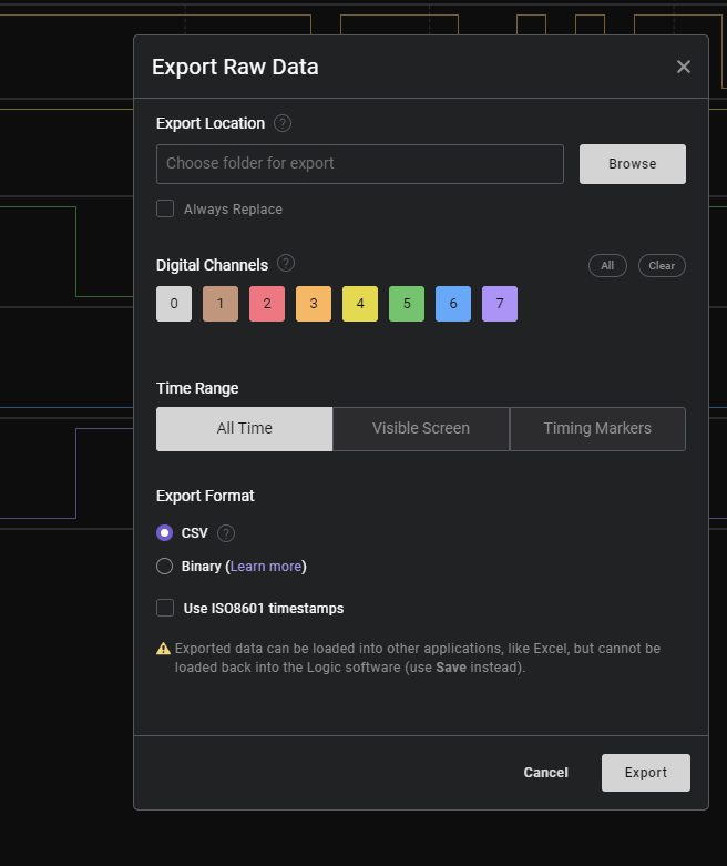
The data is exported in .csv format and now I’ll use the ultimate hacking tool: Microsoft Excel
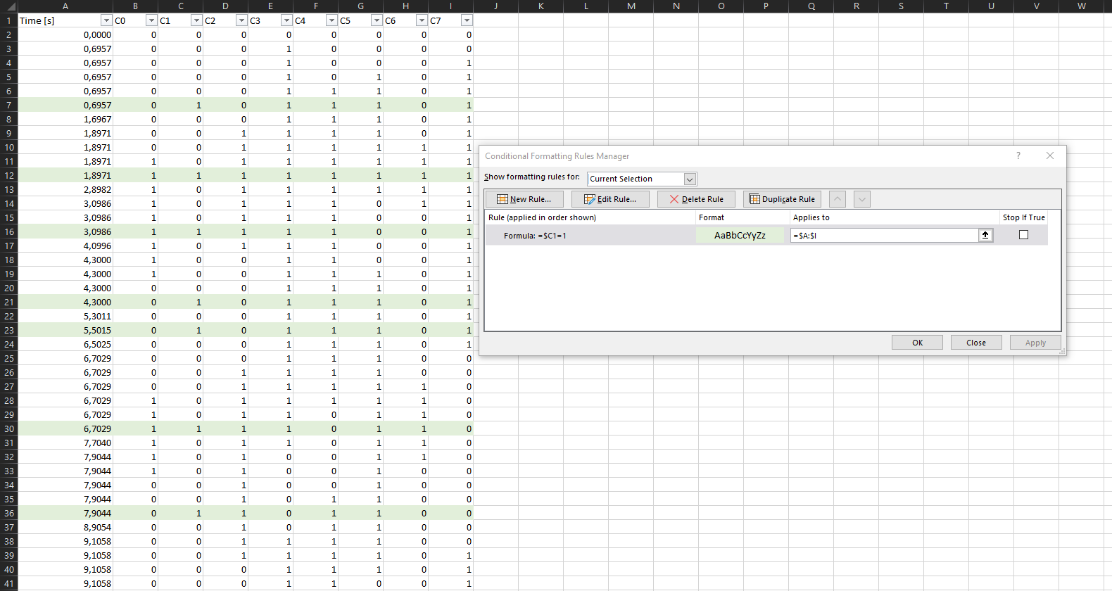
Logic2 gave me a file that has a new column every time a transition happens on any signal.
I will filter the data and display the value of each signal only when Channel1 becomes 1.
Note: Channel1 is the one we identified as our “clock signal”
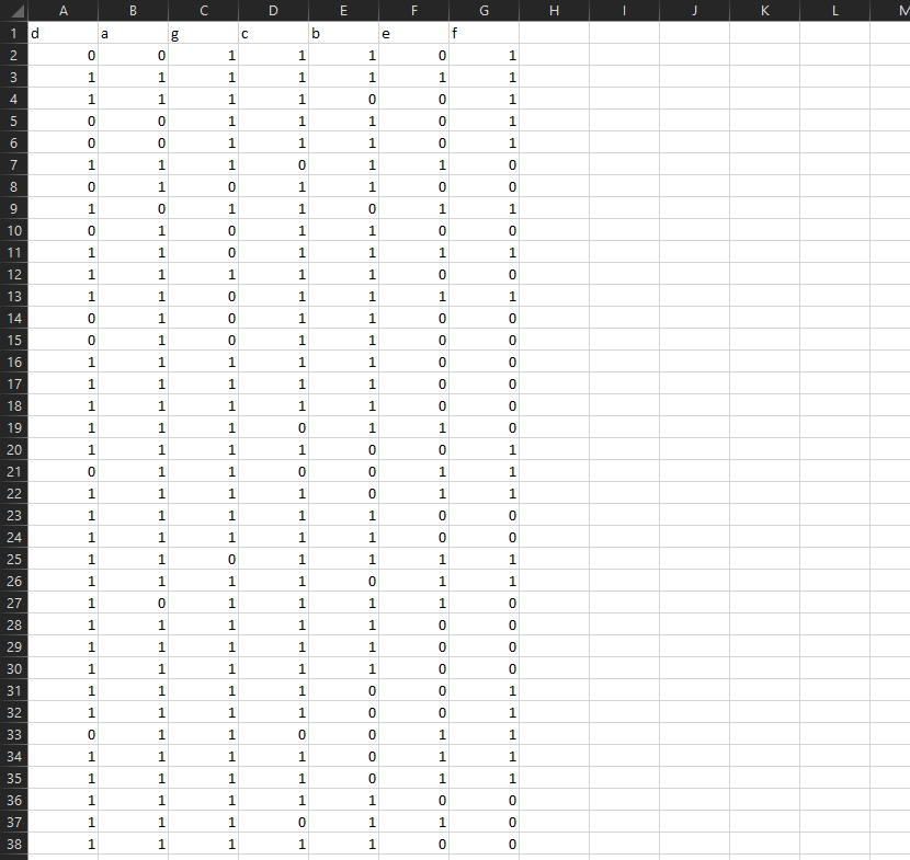
For that, I use conditional formatting and the filter “$C1=1” and color those lines
(I have C1 on column C, look at the screenshot)
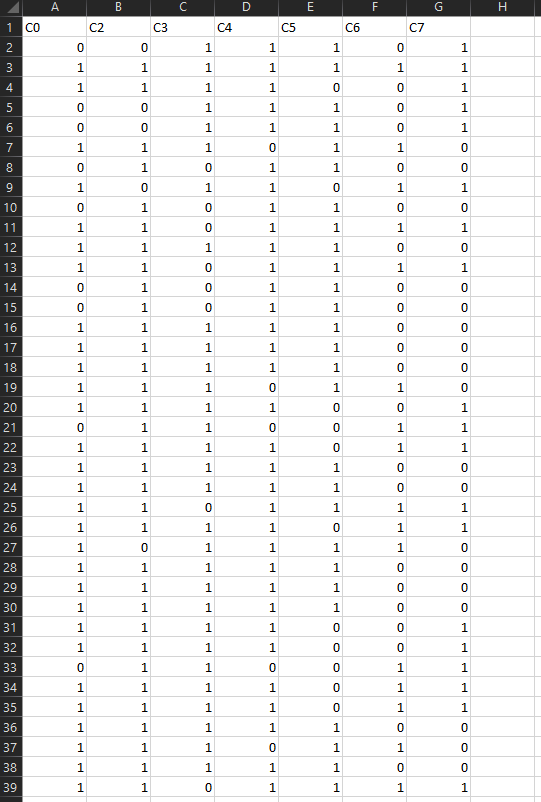
Then, I filter the lines by color and keep only the ones that I previously colored in green.
For simplicity, I move those lines to a different sheet and remove C1 because I filtered by its value so it will always be 1.
Now, I need to assign a segment to each of the signals.
After a google search about using seven segment displays, one of the first results had a possible arrangement for those pins.
The page I found can be read here
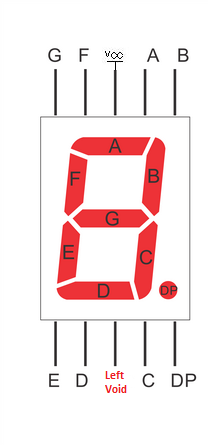
I traced the signals on the PCB and the two unlabeled signals are not data signals, so that matches our circuit for now.
Our ‘Clock signal’ (C1) is connected to the Decimal Point (DP) pin. That makes the small dot in the bottom-right corner light up.
That signal is irrelevant for displaying characters, so I think this might be good for our circuit. Let’s give it a try.
Our signals correspond to the segments on the display like this:
- C0 - Segment D
- C1 - DP (Decimal point)
- C2 - Segment A
- C3 - Segment G
- C4 - Segment C
- C5 - Segment B
- C6 - Segment E
- C7 - Segment F
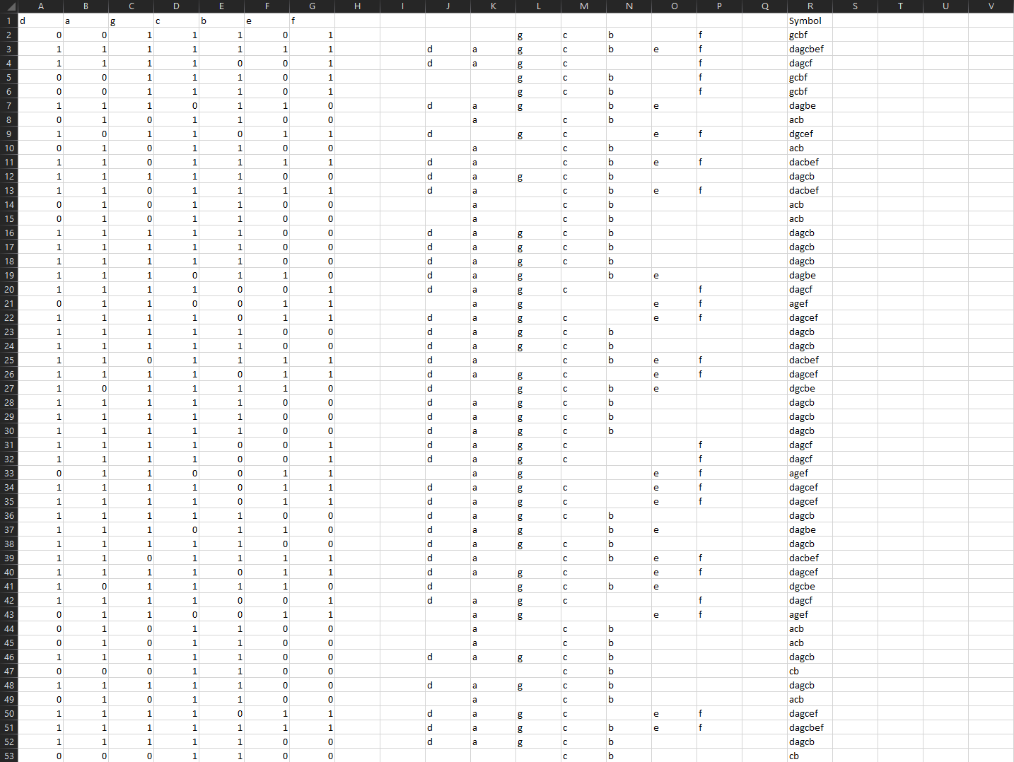
Changing the column headers in Excel will look like this
And now we need a few more things:
- first, create a function that will print the name of the segment(a/b/c/d/e/f/g) if the corresponding signal is set to ‘1’
For the first signal, it will look like this.
I made it take the name from the column header in case I want to change this later (maybe the segments aren’t correctly assigned)
=IF(A2=1; A$1; "")-
Now let’s apply this to all the segments and all the rows First, apply this formula (just drag it in Excel) to the next 6 columns so it covers all 7 segments.
Then, apply the formula (on all 7 columns) to the entire spreadsheet. -
the last thing that we need is to concatenate the output of those segments In my case, that can be done with
=CONCAT(J2:P2)The final result looks something like this:
Note: You should know that some seven segment displays will turn on their segments when the input signal is “0”, not “1”. Here I just happened to get the right one on the first try.
We can copy the notation obtained this way and use dcode.fr (https://www.dcode.fr/7-segment-display) to turn it into text.
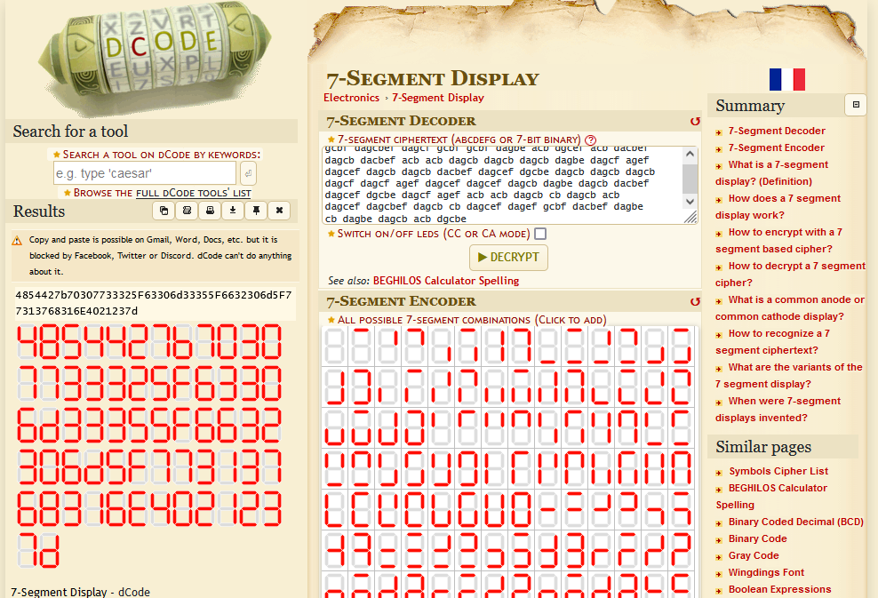
We get the following string: 4854427b70307733325F63306d33355F6632306d5F77313768316E4021237d
Which we can put into CyberChef and try to decode it (in this case, using ‘From Hex’)
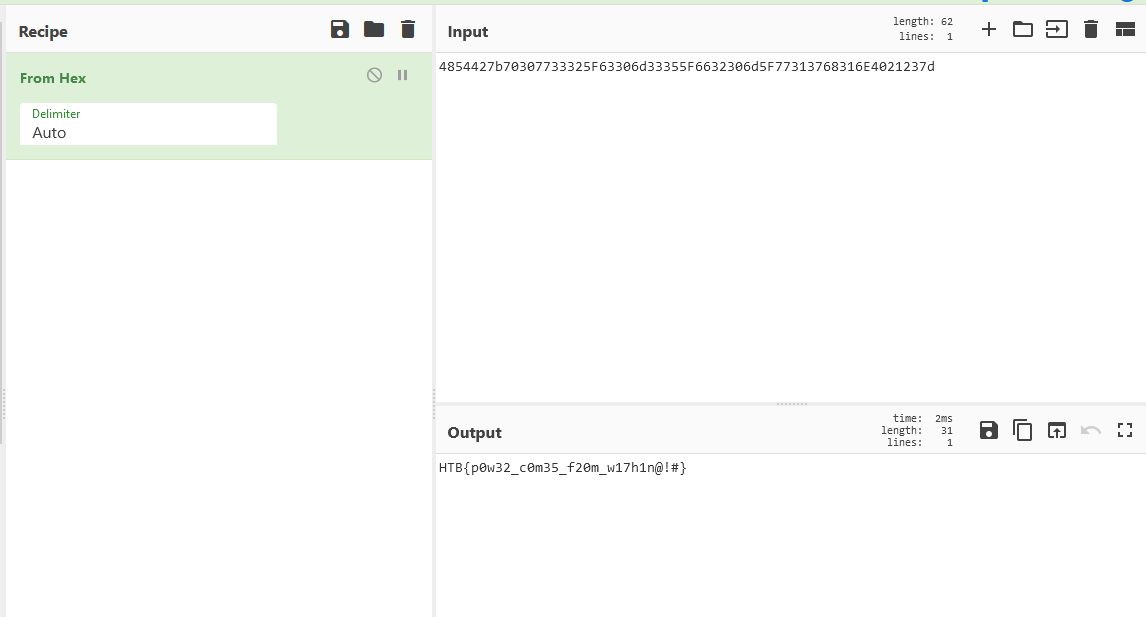
And we get our flag: HTB{p0w32_c0m35_f20m_w17h1n@!#}
More hardware challenges
These are the other hardware challenges from this CTF
- Hardware 1/5 - Very Easy - Critical Flight
- Hardware 2/5 - Very Easy - Timed Transmission
- Hardware 3/5 - Easy - Debug
- Hardware 4/5 - Easy - Secret Code (you are here)
- Hardware 5/5 - Medium - HM74